Drawing
Draw lines and put an inline inverter on a line:
In this chapter we are going to:
- Insert a symbol
- Draw a line by mouse clicks
- Place an inverter
- Give sloped lines another color/width
In the previous chapter we created some simple logic. We connected the AND gate with the inputs and output by positioning the cursor on the proper vertical position and gave an H command. This was done by either right click and clicking on the "H: Horizontal.." line in the popup, or by using the H on the keyboard.
In this chapter we will see that HCADwin has more means to do so.
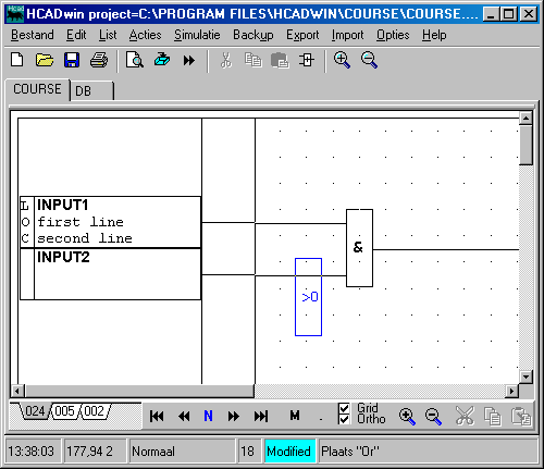 First we will extend our logic.
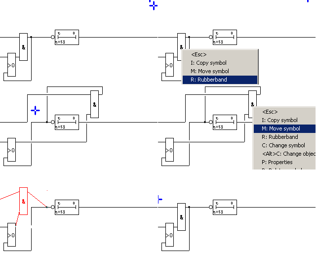
Insert a new symbol (OR gate). This is done by giving an I command NOT on a symbol and select the Or. After the second click on the symbol we can move it and it is blue. Look at the picture to see the desired position.
Note that we are going to drop it above a line. Click and see that the line is automatically cut into two lines.
Now we are going to draw some lines from the output of the AND-gate to the input of the OR-gate. Making a Set-Reset flip-flop in the process.
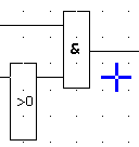
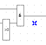
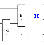
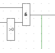
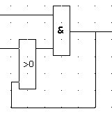
In 5 steps we will draw some lines: (Click here for an animation)
- Put cursor on an empty place and left click your mouse. The cursor shape changes.
- Don't want to draw: use Escape or right click. No mistake: Position the cursor on the starting point.
- Left click and the cursor disappears, start moving the mouse downward. Notice only horizontal and vertical movements are allowed.
- Left click on the position under the OR-gate.
- Keep left clicking and moving until you reach the input side of the or gate. Notice that the line won't cross symbols. It just stops at the proper place.
When a line should be stopped, but not on a symbol, just right click or left click again (HCADwin stops drawing lines when the line length is zero).
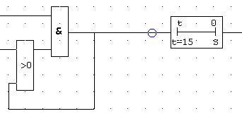 Extend your logic even more.
Put a timer in the line after the AND-gate.
I command and the first symbol (T->0) in the Timers/Counters group.
Give 15 on the posed question.
I command and the Inv symbol in the logic category.
Put the circle on the line (right from the center!) and click.
HCADwin will put it on the proper place. As a shortcut, the I command on a line will toggle an invertor.
Just to see what happens: As an example draw a line from underneath the timer to nowhere. Notice this line will be thicker and magenta. It transports not a Boolean, but a real value.
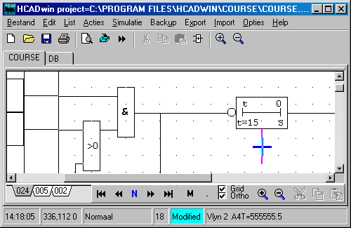
Note that the cursor is put on the vertical line and the status bar of HCADwin shows: "Vlyn 2 A4T=555555.5".
It is an indication that the cursor is on a symbol with mnemonic Vlyn. The 2 means: second signal (not relevant here). The "A4T" means that this signal has that name. (it comes from the fourth symbol we have drawn, the timer, and it is the Timing value.) The value itself indicates that is has never been updated.
Using the same input tag again:
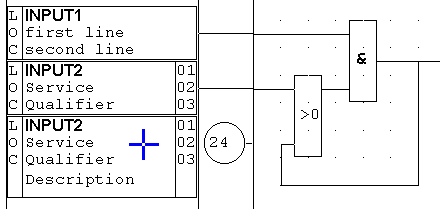 As an example how HCADwin can draw inputs, look at the picture on the left.
Intentionally an extra input with the same tag is added. Note that a circle with the page number on which the first occurrence of that tag was seen appears at the second (and third, and fourth, and ...) input.
Note also that with the Change command the second input was stretched vertically to give way for the description field as well.
The first note is that the "Rack" field while entering additional data for the tag, was filled with the string: "RPC:01-02-03", meaning: the Rack, Position, Channel to indicate the location of the input in the assumed PLC. This data can be used when the functional logical description as drawn by HCADwin, is used to indicate the ASBUILT information also.
NB. When the tag was used as an output (also), the last page number will appear. This reflects the output status as if it were a PLC output the most.
As an exercise do the following:
Draw many lines which are connected and crossing. Notice how vertical lines automatically give way for the horizontal ones.
Try M, C, D, Y and R commands on lines. Notice how the D and Y commands both delete but differ.
Also try to connect to output sides of the AND and OR gates to each other. The short-circuit lines will be colored red.
 Non connecting lines:
Click on both Grid and Ortho checkboxes in order to allow the cursor off grid and lines being drawn in any direction.
Notice that the cursor will be green instead of blue when it is not on a grid position.
Start drawing lines now by mouse clicks and movement. Stop after drawing two lines.
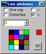
Use the C command on the last line. You will notice the popup window as shown here on the right. Click on the red square for the line color, set the line width to 3 and activate the right arrow. After clicking OK you will see two lines with different attributes.
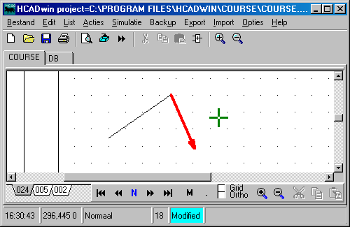
When giving the dotted attribute the width be always be "1". The right arrow will be downward when the line is exactly vertical. When then line is drawn vertically, it can be useful that it gives way for horizontal lines. In that case set the left upper checkbox on (=Give way).
Notice the green cursor and the status of the Grid and Ortho checkboxes.
When drawing new lines this way, the last attributes will be in effect.
Try the M command on these lines. You will see that it will rubberband on your mouse. Which side will depend on which end you were closest when clicking. Try it!
When giving a D command with the cursor on both lines, a selection window will popup. You'll be forced to choose one. Note that all objects are colored aqua except for the chosen one (red). HCADwin always deals with one symbol at the time.
These non connecting lines will never transport output values from symbols to another. It is possible to convert the Hlyn en Vlyn to the Slyn (these are the mnemonics for the Horizontal, Vertical and Slope lines) and back. Use the \ and the [ commands. The latter will AutoRoute the Slyn into several ortho lines, but only if start and endpoints were on grid positions.
What we have learned:
- Drawing lines can be done by H or V commands, but also by clicking and moving the mouse.
- Symbols can be placed on top of lines which will be cut.
- Placing inverters will be supported by some intelligence.
- Line types are generated automatically, it depends on the source symbol and position of the connection.
- All symbols have the upper and left side as input area's, the right and bottom side as output areas. Short circuit lines are detected.
- When drawing off grid and/or not ortho, lines will loose their connecting powers, but gain in attributes. These lines are used for mere drawing purposes.
- The delete commands D and Y differ slightly. Use the Y for deleting signals and D for symbols or single lines.
- The M, C, R commands work nicely on lines. When doing so the color of the line indicates what's going on. The R command shortens or lengthens connecting lines. The C command extends a line upto the next symbol.

